
Upgrade Motorsport Brake Bias / Balance Valve Correct Fittings & Torque Settings Installation Guide
- Oct 25, 2025
- 4 min read
Updated: Feb 6
Correct Fittings & Torque Settings Installation Guide For Screw-Type and Lever-Type Motorsport Brake Bias / Balance Valves (2 × M10x1.0 Female Fittings)
Both Upgrade Motorsport brake bias / balance valves allow you to finely adjust front-to-rear brake pressure balance, giving total control of pedal feel and braking performance for track, rally, and competition applications.
The Screw-Type Valve provides precise incremental adjustment for fixed or pre-set applications, while the Lever-Type Valve offers on-the-fly bias adjustment, ideal for track and rally drivers who need to fine-tune braking mid-session.
Correct installation is essential for achieving consistent brake pressure, reliable pedal feel, and a leak-free hydraulic system.

Why This Guide Matters
We’ve recently seen a few customers experience fitment issues, including stripped threads and minor fluid leaks, during installation.These problems are almost always caused by incorrect fitting, incorrect torque, using the wrong flare type, or over-tightening the M10 fittings.
To help prevent this, we’ve created this detailed Upgrade Motorsport Bias Valve Correct Fittings & Torque Settings Installation Guide. In this guide we cover the correct fittings, torque settings, and step-by-step procedures for both the Screw-Type and Lever-Type valves to ensure a safe, leak-free installation every time.
Required Tools & Fittings
Tool / Component | Notes |
10 mm & 11 mm Spanners | Flare-nut type preferred |
Brake Fluid | DOT 4 or DOT 5.1 high-performance fluid |
Brake Bleeding Kit | For full system bleed |
M10x1.0 Lines & Fittings | For flexible braided lines |
M10x1.0 Hardline Fittings | For copper lines |
Mounting Hardware | M6 bolts or tunnel clip |
Thread Sealant / PTFE | Only for tapered fittings – not required for AN fittings |
Understanding the Ports
Each valve includes two M10 × 1.0 female ports clearly labelled IN and OUT.
IN (Inlet): Connects to the rear master cylinder outlet or rear line from the pedal box.
OUT (Outlet): Connects to the rear brake circuit or T-piece feeding both rear calipers.
💡 Tip: Always install the bias valve in the rear brake line only, never the front.

Fitting Type & Sealing
Your Upgrade Motorsport bias valve is compatible with:
M10x1.0 (37° flare) – for braided lines
M10 × 1.0 hardline fittings (DIN bubble flare) – for copper pipework
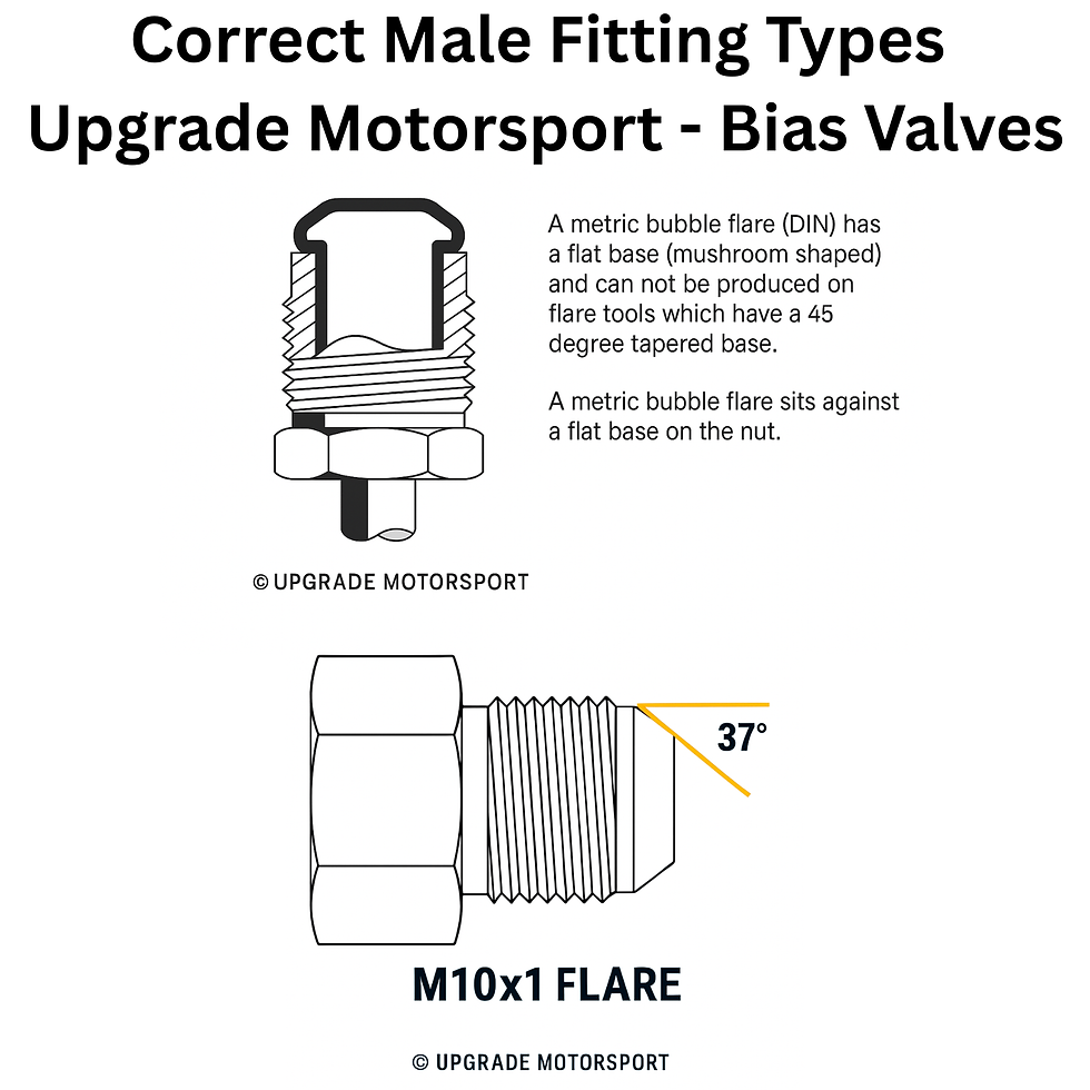
M10x1 (37° Flare) Fittings
Creates a metal-to-metal seal, no washer or sealant required
Ensure both faces are clean and burr-free
Tighten to 16–19 Nm
Ideal for high-performance and motorsport applications

M10 × 1.0 Hardline (DIN bubble flare)
Use a DIN bubble flare for a proper seat
Tighten to 14–16 Nm
Use a copper washer if sealing surface requires it

Mounting Location
Mount the valve inline on the rear brake circuit after the rear master cylinder and before the rear brake T-piece.
Recommended Mounting Positions:
Screw-Type Valve: On the chassis tunnel or dashboard panel within easy reach of the driver for live adjustment
Lever-Type Valve: On the chassis tunnel or dashboard panel within easy reach of the driver for live adjustment
Ensure the adjustment screw or lever is easily accessible but protected from accidental movement or debris.

Installation Steps
Depressurise the System
Remove the brake reservoir cap.
Pump the pedal several times to release pressure.
Prepare the Lines
Flare the ends using the correct tool:
37° single flare for M10x1.0
DIN bubble flare for M10x1.0 fittings
Deburr and clean threads.
Connect the Inlet Port
Attach the line from the rear master cylinder outlet to the IN port.
Connect the Outlet Port
Attach the line from the OUT port to the rear brake line or T-piece.
Secure Mounting
Fix the valve using M6 bolts or brackets.
Avoid tension on brake lines.
Bleed the Brakes
Refill reservoir and bleed thoroughly starting with the rear calipers.
Check for leaks at all connections.
Check out the Upgrade comprehensive bias valve bleeding guide.
Set Initial Bias
Screw-Type Valve:
Clockwise = Reduces rear brake pressure
Anticlockwise = Increases rear brake pressure
Start mid-range and fine-tune during testing.
Lever-Type Valve:
Pulling lever towards the rear = Increases rear pressure
Pushing lever forward = Reduces rear pressure
Start mid-range and fine-tune during testing.
Testing & Adjustment
Test at low speed on a safe surface.
Adjust incrementally to find the best brake balance.
Avoid excessive rear bias which can cause rear lock-up.

Maintenance
Component | Inspection Frequency | Action |
Valve Body | Every 6 months | Check for leaks or corrosion |
Fittings | Each service | Tighten and inspect for damage |
Adjustment Screw / Lever | Every event | Clean and lubricate threads |
Brake Fluid | Every 6–12 months | Replace with fresh DOT 4 / 5.1 |
Torque & Pressure Reference
Component | Torque (Nm) | Notes |
AN-3 Male Fitting | 16–19 Nm | Metal-to-metal seal |
M10 × 1.0 Hardline | 14–16 Nm | Use washer if needed |
Valve Mounting Bolts (M6) | 6–8 Nm | Use Nyloc or Loctite 243 |
Final Checks
✅ Check for leaks at all fittings
✅ Confirm free movement of screw or lever
✅ Ensure valve is securely mounted
✅ Lines must not be twisted or under stress
✅ Test brake balance progressively before competition use
Summary
Both Screw-Type and Lever-Type Upgrade Motorsport Bias Valves provide precise, reliable control of rear brake pressure for competition and performance applications.
For best results:
Use M10x1 stainless braided lines with 37° flare fittings
Mount securely along the chassis tunnel
Bleed thoroughly and test gradually
This combination delivers a consistent, vibration-resistant metal-to-metal seal and the ultimate in adjustability for track, drift, and rally performance.
Next Step: Earn Rewards on Every Order
Join the Upgrade Loyalty Programme and collect points with every purchase.
💥 Earn 50 points instantly at checkout and double value rewards during special events like Black Friday and Birthday Month.
Liability Notice
All Upgrade Motorsport products must be installed and used by competent individuals familiar with automotive hydraulic systems. Incorrect installation or misuse can result in component failure, serious injury, or death.Upgrade Motorsport accepts no liability for any personal injury, death, loss, or damage arising from the installation, modification, or use of its products. It is the user’s sole responsibility to ensure correct fitment, maintenance, and operation in accordance with motorsport and safety regulations.


Comments